8.2. Configuration of hardware and drivers#

8.2.1. Available kernel variants#

The standard kernel in UCS 5.0 is based on the Linux kernel 4.19. In principle, there are three different types of kernel packages:

  • A kernel image package provides an executable kernel which can be installed and started.

  • A kernel source package provides the source code for a kernel. From this source, a tailor-made kernel can be created, and functions can be activated or deactivated.

  • A kernel header package provides interface information which is required by external packages if these have to access kernel functions. This information is usually necessary for compiling external kernel drivers.

Normally, the operation of a UCS system only requires the installation of one kernel image package.

Several kernel versions can be installed in parallel. This makes sure that there is always an older version available to which can be reverted in case of an error. So-called meta packages are available which always refer to the kernel version currently recommended for UCS. In case of an update, the new kernel version will be installed, making it possible to keep the system up to date at any time.

8.2.2. Hardware drivers / kernel modules#

The boot process occurs in two steps using an initial RAM disk (initrd for short). This is composed of an archive with further drivers and programs.

The GRUB boot manager (see GRUB boot manager) loads the kernel and the initrd into the system memory, where the initrd archive is extracted and mounted as a temporary root file system. The real root file system is then mounted from this, before the temporary archive is removed and the system start implemented.

The drivers to be used are recognized automatically during system start and loaded via the udev device manager. At this point, the necessary device links are also created under /dev/. If drivers are not recognized (which can occur if no respective hardware IDs are registered or hardware is employed which cannot be recognized automatically, e.g., ISA boards), kernel modules to be loaded can be added via Univention Configuration Registry Variable kernel/modules. If more than one kernel module is to be loaded, these must be separated by a semicolon. The Univention Configuration Registry Variable kernel/blacklist can be used to configure a list of one or more kernel modules for which automatic loading should be prevented. Multiple entries must also be separated by a semicolon.

Unlike other operating systems, the Linux kernel (with very few exceptions) provides all drivers for hardware components from one source. For this reason, it is not normally necessary to install drivers from external sources subsequently.

However, if external drivers or kernel modules are required, they can be integrated via the DKMS framework (Dynamic Kernel Module Support). This provides a standardized interface for kernel sources, which are then built automatically for every installed kernel (insofar as the source package is compatible with the respective kernel). For this to happen, the kernel header package linux-headers-amd64 must be installed in addition to the dkms package. Please note that not all the external kernel modules are compatible with all kernels.

8.2.3. GRUB boot manager#

In Univention Corporate Server GNU GRUB 2 is used as the boot manager. GRUB provides a menu which allows the selection of a Linux kernel or another operating system to be booted. GRUB can also access file systems directly and can thus, for example, load another kernel in case of an error.

GRUB menu

Fig. 8.3 GRUB menu#

GRUB gets loaded in a two-step procedure; in the Master Boot Record of the hard drive, the Stage 1 loader is written which refers to the data of Stage 2, which in turn manages the rest of the boot procedure.

The selection of kernels to be started in the boot menu is stored in the file /boot/grub/grub.cfg. This file is generated automatically; all installed kernel packages are available for selection. The memory test program Memtest86+ can be started by selecting the option Memory test and performs a consistency check for the main memory.

There is a five second waiting period during which the kernel to be booted can be selected. This delay can be changed via the Univention Configuration Registry Variable grub/timeout.

By default a screen size of 800x600 pixels and 16 Bit color depth is preset. A different value can be set via the Univention Configuration Registry Variable grub/gfxmode. Only resolutions are supported which can be set via VESA BIOS extensions. A list of available modes can be found in VESA BIOS Extensions. The input must be specified in the format HORIZONTALxVERTICAL@COLOURDEPTHBIT, so for example 1024x768@16.

Kernel options for the started Linux kernel can be passed with the Univention Configuration Registry Variable grub/append. Univention Configuration Registry Variable grub/xenhopt can be used to pass options to the Xen hypervisor.

The graphic representation of the boot procedure - the so-called splash screen - can be deactivated by setting Univention Configuration Registry Variable grub/bootsplash to nosplash.

8.2.4. Network configuration#

The configuration of network interfaces can be adjusted with the UMC module Network settings.

The configuration is saved in Univention Configuration Registry variables, which can also be set directly. These variables are listed in the individual sections.

Configuring the network settings

Fig. 8.4 Configuring the network settings#

All the network cards available in the system are listed under IPv4 network devices and IPv6 network devices (only network interfaces in the ethX scheme are shown).

Network interfaces can be configured for IPv4 and/or IPv6. IPv4 addresses have a 32-bit length and are generally written in four blocks in decimal form (e.g., 192.0.2.10), whereas IPv6 addresses are four times as long and typically written in hexadecimal form (e.g., 2001:0DB8:FE29:DE27:0000:0000:0000:0000).

8.2.4.1. Configuration of IPv4 addresses#

If the Dynamic (DHCP) option was not chosen, the IP address to be bound to the network card must be entered. In addition to the IPv4 address the net mask must also be entered. DHCP query is used to request an address from a DHCP server. Unless the Dynamic (DHCP) option is activated, the values received from the DHCP request are configured statically.

Server systems can also be configured via DHCP. This is necessary for some cloud providers, for example. If the assignment of an IP address for a server fails, a random link local address (169.254.x.y) is configured as a replacement.

For UCS server systems the address received via DHCP is also written to the LDAP directory.

Note

Not all services (e.g., DNS servers) are suitable for use on a DHCP-based server.

UCR variables:

Besides the physical interfaces, additional virtual interfaces can also be defined in the form interfaces/ethX_Y/setting.

8.2.4.2. Configuration of IPv6 addresses#

The IPv6 address can be configured in two ways: Stateless address autoconfiguration (SLAAC) is employed in the Autoconfiguration (SLAAC) configuration. In this, the IP address is assigned from the routers of the local network segment. Alternatively, the address can also be configured statically by entering the IPv6 address and IPv6 prefix.

In contrast to DHCP, in SLAAC there is no assignment of additional data such as the DNS server to be used. There is an additional protocol for this (DHCPv6), which, however, is not employed in the dynamic assignment. One network card can be used for different IPv6 addresses. The Identifier is a unique name for individual addresses. The main address always uses the identifier default; functional identifiers such as Interface mail server can be assigned for all other addresses.

UCR variables:

Further network settings can be performed under Global network settings.

The IP addresses for the standard gateways in the subnetwork can be entered under Gateway (IPv4) and Gateway (IPv6). It is not obligatory to enter a gateway for IPv6, but recommended. A gateway configured here has preference over router advertisements, which might otherwise be able to change the route.

UCR variables:

8.2.4.3. Configuring the name servers#

There are two types of DNS servers:

External DNS Server

An External DNS Server is employed for the resolution of host names and addresses outside of the UCS domain, e.g., univention.de. This is typically a name server operated by the internet provider.

Domain DNS Server

A Domain DNS Server is a local name server in the UCS domain. This name server usually administrates host names and IP addresses belonging to the UCS domain. If an address is not found in the local inventory, an external DNS server is automatically requested. The DNS data are saved in the LDAP directory service, i.e., all domain DNS servers deliver identical data.

A local DNS server is set up on the Primary Directory Node, Backup Directory Node and Replica Directory Node system roles. Here, you can configure which server should be primarily used for the name resolution by entering the Domain DNS Server.

UCR variables:

8.2.4.4. Bridges, bonding, VLANs#

UCS supports advanced network configurations using bridging, bonding and virtual networks (VLAN):

  • Bridging is often used with virtualization to connect multiple virtual machines running on a host through one shared physical network interface.

  • Bonding allows failover redundancy for hosts with multiple physical network interfaces to the same network.

  • VLANs can be used to separate network traffic logically while using only one (or more) physical network interface.

8.2.4.5. Configure bridging#

The most common application scenario for bridging is the shared use of a physical network card by one or more virtual machines. Instead of one network card for each virtual machine and the virtualization server itself, all systems are connected via a shared uplink. A bridge can be compared with a switch implemented in software which is used to connect the individual hosts together. The hardware network adapter used is called a bridge port.

In order to configure a bridge, Bridge must be selected as the Interface type under Add. The Name of new bridge interface can be selected at will. Then click on Next.

The physical network card intended to act as the uplink can be selected under Bridge ports. In the typical scenario of connecting virtual machines via just one network card, there is no risk of a network loop. If the bridge is used to connect two Ethernet networks, the spanning tree protocol (STP) is employed to avoid network loops. The Linux kernel only implements STP, not the Rapid STP or Multiple STP versions.

The Forwarding delay setting configures the waiting time in seconds during which information is collected about the network topology when a connection is being made via STP. If the bridge is used for connecting virtual machines to one physical network card, STP should be disabled by setting the value to 0. Otherwise problems may occur when using DHCP, as the packets sent during the waiting time are not forwarded.

The Additional bridge options input field can be used to configure arbitrary bridge parameters. This is only necessary in exceptional cases; an overview of the possible settings can be found on the manual page bridge-utils-interfaces(5).

Clicking on Next offers the possibility of optionally assigning the bridge an IP address. This interface can then also be used as a network interface for the virtualization host. The options are the same as described in Configuration of IPv4 addresses and Configuration of IPv6 addresses.

8.2.4.6. Configure bonding#

Bonding can be used to bundle two (or more) physical network cards in order to increase the performance or improve redundancy in failover scenarios.

In order to configure a bonding, Bonding must be selected as the Interface type under Add. The Name of the bonding interface can be selected at will. Then click on Next.

The network cards which form part of the bonding interface are selected under Bond slaves. The network cards which should be given preference in failover scenarios (see below) can be selected via Bond primary.

The Mode configures the distribution of the network cards within the bonding:

  • balance-rr (0) distributes the packets equally over the available network interfaces within the bonding one after the other. This increases performance and improves redundancy. In order to use this mode, the network switches used must support link aggregation.

  • When active-backup (1) is used, only one network card is active for each bonding interface (by default this is the network interface configured in Bond primary). If the primary network card fails, this is detected by the Linux kernel, which switches to another card in the bonding. This version increases redundancy. It can be used with every network switch.

In addition, there are also a number of other bonding methods. These are generally only relevant for special cases and are described under Linux Ethernet Bonding Driver HOWTO.

The Media Independent Interface (MII) of the network cards is used to detect failed network adapters. The MII link monitoring frequency setting specifies the testing interval in milliseconds.

All other bonding parameters can be configured under Additional bonding options. This is only necessary in exceptional cases; an overview of the possible settings can be found under Linux Ethernet Bonding Driver HOWTO.

Clicking on Next allows to optionally assign the bonding interface an IP address. If one of the existing network cards which form part of the bonding interface has already been assigned an IP address, this configuration will be removed. The options are the same as described in Configuration of IPv4 addresses and Configuration of IPv6 addresses.

8.2.4.7. Configure VLAN#

VLANs can be used to separate the network traffic in a physical network logically over one or more virtual subnetworks. Each of these virtual networks is an independent broadcast domain. This makes it e.g. possible to differentiate between a network for the employees and a guest network for visitors in a company network although they use the same physical cables. The individual end devices can be assigned to the VLANs via the configuration of the switches. The network switches must support 802.1q VLANs.

A distinction is made between two types of connections between network cards:

  • A connection only transports packets from a specific VLAN. In this case, untagged data packets are transmitted.

    This is typically the case if only one individual end device is connected via this network connection.

  • A connection transports packets from several VLANs. This is also referred to as a trunk link. In this case, each packet is assigned to a VLAN using a VLAN ID. During transmission between trunk links and specific VLANs, the network switch takes over the task of filtering the packets by means of the VLAN IDs as well as adding and removing the VLAN IDs.

    This type of connection is primarily used between switches/servers.

    Some switches also allow the sending of packets with and without VLAN tags over a shared connection, but this is not described in more detail here.

When configuring a VLAN in the UMC module Network settings it is possible to configure for a computer which VLANs it wants to participate in. An example here would be an internal company web server, which should be available both to the employees and any users of the guest network.

In order to configure a VLAN, Virtual LAN must be selected as the Interface type under Add. The network interface for which the VLAN is specified with Parent interface. The VLAN ID is the unique identifier of the VLAN. Valid values are from 1 to 4095. Then Next must be clicked.

Clicking on Next allows to optionally assign the VLAN interface an IP address. The options are the same as described in Configuration of IPv4 addresses and Configuration of IPv6 addresses. When assigning an IP address, ensure that the address matches the assigned VLAN address range.

8.2.5. Proxy access configuration#

The majority of the command line tools which access web servers (e.g., wget, elinks or curl) check whether the environment variables http_proxy or https_proxy are set. If this is the case, the proxy server set in these variables is used automatically.

The Univention Configuration Registry Variable proxy/http and proxy/https can also be used to activate the setting of these environment variables through an entry in /etc/profile.

The proxy URL must be specified for this, for example http://192.0.2.100. The proxy port can be specified in the proxy URL using a colon, for example http://192.0.2.100:3128. If the proxy requires authentication, this can be provided in the form http://username:password@192.0.2.100.

The environment variable is not adopted for sessions currently opened. A new login is required for the change to be activated.

The Univention tools for software updates also support operation via a proxy and query the Univention Configuration Registry variable.

Individual domains can be excluded from use by the proxy by including them separated by commas in the Univention Configuration Registry Variable proxy/no_proxy. Subdomains are taken into account; e.g. an exception for software-univention.de also applies for updates.software-univention.de.

8.2.6. Mounting NFS shares#

The NFS mounts policy of the UMC computer management can be used to configure NFS shares, which are mounted on the system. There is a NFS share for selection, which is mounted in the file path specified under Mount point.
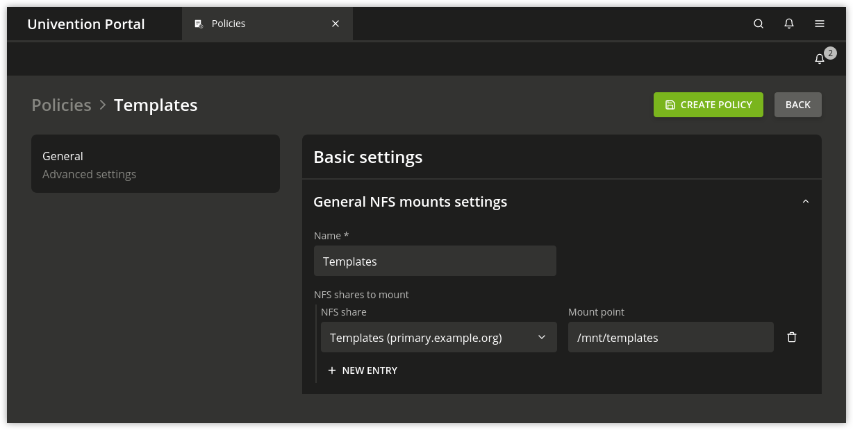
Mounting a NFS share

Fig. 8.5 Mounting a NFS share#

8.2.7. Collection of list of supported hardware#

Univention collects information about hardware which is compatible with UCS and in use by customers. The information processed for this is gathered by the UMC module Hardware information.

All files are forwarded to Univention anonymously and only transferred once permission has been received from the user.

The start dialogue contains the entry fields Manufacturer and Model, which must be completed with the values determined from the DMI information of the hardware. The fields can also be adapted and an additional Descriptive comment added.

If the hardware information is transferred as part of a support request, the This is related to a support case option should be activated. A ticket number can be entered in the next field; this facilitates assignment and allows quicker processing.

Clicking on Next offers an overview of the transferred hardware information. In addition, a compressed TAR archive is created, which contains a list of the hardware components used in the system and can be downloaded via Archive with system information.

Clicking on Next again allows you to select the way the data are transferred to Univention. Upload transmits the data via HTTPS, Send mail) opens a dialogue, which lists the needed steps to send the archive via email.